Motor isolation base is not new to those who follow my blog. So far many have ventured into doing this new tweak seeing the importance of isolating the plinth from the motor vibrations. It's really worthwhile as the sonic improvement is undoubtedly significant. It works wonders to your deck, be it with 110V old motor (Planars, P1, P2 ... ) or 24V new motor (P3/24, P5... ). The installation is considered straight forward, even for anyone without DIY skills.
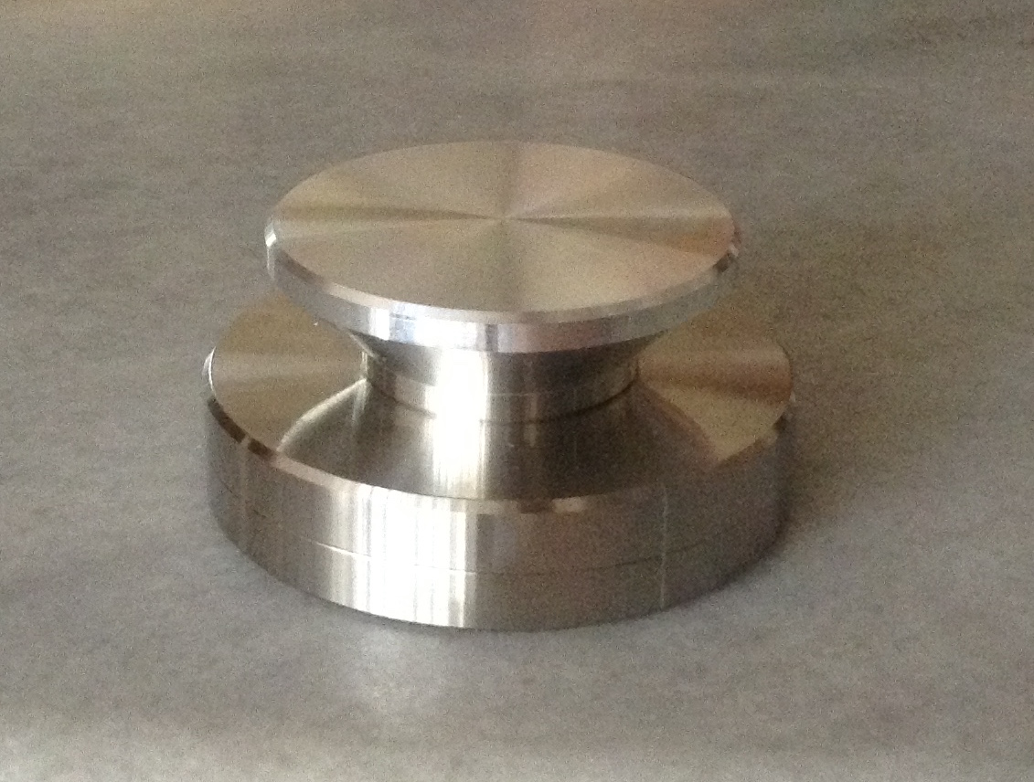
There you are, the shining looking stainless steel motor base after installation (without the rubber mesh).
However, there must be a way to hold the motor and base assembly in place during transportation since it's not fixed to the plinth anymore. The simplest solution I could think of is by attaching a piece of rubber mesh which cuddles it loosely to the plinth (using the existing screw holes for the motor cover). In this case there is no drilling involved and it's also a reversible tweak.
Alternatively, for the handyman, I have also recommended my DIY
out-board motor . The only setback is this tweak requires a bit of soldering and DIY skills, i.e. you have to dismantle the pcb (printed circuit board) and power supply cables in order to have a completely detached motor assembly.
This may look daunting to some of you, but it's definitely not more difficult compared with doing a new motor upgrade which many of you have done!
As for my RP6, I am doing it in another way without the rubber mesh also. The motor assembly is now made detachable from the pcb (printed circuit board) by adding a 4-way connector to it. Just unplug the connector to the motor/base assembly whenever there's a need to move the deck around. And snap it back after relocation. Easy?
Adding a 4-way connector
The procedure is as follows:
All you need to do is to cut the motor wires half way and then reconnect the four wires back using the 4-way connector as shown. No soldering is required, just a plier to cut and clamp the wires to the connector. *( Of course don't cut if you can solder, read notes below.)
Don't you think it looks good and convenient to use?
Try it out on your motor base if you are tired of the look of the rubber mesh now!
Note: If you have soldering skill it might be better to desolder the motor wires from the control printed circuit board (pcb) instead of cutting as I have done. Get some similar size wires ( about 6" or 150mm in length) and solder them to the pcb. Then add the 4-way connector to both the open ends. In this case, it's reversible too.